
The new waveform steel web combined box girder bridge (the bottom plate is steel) can make the performance of steel and concrete materials into full play, reasonably improve the stress performance of the structure, and effectively avoid the drawbacks of easy cracking of the concrete bottom plate. Replacing the concrete bottom plate with steel bottom plate can significantly reduce the deadweight of box girder, improve the spanning capacity, facilitate on-site transportation and erection, and improve the service life of the bridge [1]–[3]. Corrugated steel web box girder is a steel mixed structure, corrugated steel web instead of the traditional concrete web, the web material, shape change at the same time, its thickness is also reduced a lot, the steel web support for the bridge deck plate is weaker than the concrete web support for the bridge deck plate. Therefore, the constraints of corrugated steel web combined box girder deck slab and the distortion and torsion of box girder closed frame are different compared with concrete box girder, and the transverse internal force of corrugated steel web box girder deck slab and concrete box girder deck slab will be changed compared with the concrete box girder deck slab [4]–[6].
In recent years, with the increase of transportation and logistics demand, the width of highway bridges and urban bridges is increasing, and the wide single-box multi-chamber corrugated steel web PC composite box girder bridge has been more and more widely used [7], [8]. Up to now, the number of bridges with more than 2 box chambers of corrugated steel web PC combined box girder bridges has reached 30 bridges in China. The statistics of constructed and under construction corrugated steel web PC composite box girder bridges show that the span diameter of corrugated steel web PC composite box girder bridges is more than 50m, based on economic and technical rationality considerations, it is preferable to use the variable height structural form and segmental cantilever construction technology [9]–[11]. Therefore, the study of the spatial mechanical properties of variable height single box multi-chamber corrugated steel web PC box girder bridge has become a key concern at present [12].
The design and analysis of corrugated steel web PC composite box girder bridges mostly use spatial rod system model, seven-degree-of-freedom single girder model and corrugated steel box girders, planar girder lattice model, solid finite element model, and spatial mesh model. However, the spatial rod system model lacks spatial effect refinement analysis, and cannot accurately describe the shear hysteresis effect, constrained torsion effect and distortion effect [13], [14]. The seven-degree-of-freedom single-beam model adds warping double moments on the basis of the original six-degree-of-freedom spatial rod system model, which analyzes the distribution of superstatic shear flow in thin-walled box girder cross-section, and the computational scale does not increase significantly compared with the traditional six-degree-of-freedom spatial rod system model, with the disadvantage that the spatial effects (e.g., shear hysteresis effect and distortion effect) cannot be analyzed in a refined way [15], [16]. The advantage of the planar beam lattice method is that it can reflect the difference of positive stresses in the cross-section, and the disadvantage is that it cannot accurately analyze the two-dimensional force of the structure subjected to shear and torsion and the accurate distribution of shear flow in the top and bottom slabs, and it is unable to take into account the out-of-plane effect of the local force in the top and bottom slabs themselves. The solid finite element model can accurately describe the spatial mechanical properties of the bridge structure, however, the solid finite element calculation results are difficult to match the calculation of the construction stage, shrinkage creep, live load loading and other design requirements, and the analysis results are the overall stress results under a variety of deformations, which do not match the internal reinforcement design method of the current specification, and it is difficult to target the structural reinforcement [17]–[19]. In addition, the process of integrating the solid unit analysis results to obtain the structural internal force is complicated and cumbersome, which limits its wide application in design and is often applied only in local analysis.
The spatial grid model can discretize a complex bridge structure into one composed of multiple plates, each plate element consists of a cross-crossing orthogonal beam lattice, and the stiffness of the cross-crossing longitudinal and transverse beams (six-degree-of-freedom beam units) is used to replace the plate stiffness, and a piece of orthogonal beam lattice is just like a “net”, and the number of plates constituting a structure can be expressed as many “nets” using the beam lattice. A structure consists of how many plates, can be expressed by the beam lattice into how many “nets”. When using spatial mesh model to simulate complex structural bridges, such as variable height single-box multi-compartment corrugated steel web PC combined box girder bridge, the modeling process is cumbersome and not easy to be mastered by engineering designers [20]–[22].
The research object of this paper is a partial cable-stayed bridge with extra large span, and there are fewer engineering cases and less research content in this spanning interval at present. Through the derivation of mechanical property checking formulae and the simulation of spatial finite element model, it provides the guiding methods and ideas for the structural design work of corrugated steel web box girders in modern bridges. Combining the main girder structure and the characteristics of corrugated steel web plate in modern bridges, the symmetric load of automobile is set as working condition 1, while the eccentric load of automobile is working condition 2, and the prestressing system and spatial finite element model are formed respectively. A mega-span partial cable-stayed bridge was selected as the research object, and the spatial finite element model constructed above was applied to study the mechanical performance of corrugated steel web box girders in three directions, namely, flexural ultimate load capacity, shear buckling, and shear stress strength.
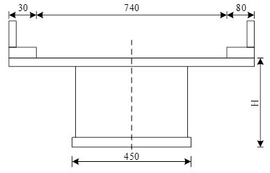
According to the structural calculation and reference to similar projects, the middle pier pivot girder height is 5.5m, the side pier pivot and span girder height is 2.6m, the girder height is varied according to two parabolic changes, the height-to-span ratio is 1/16.44 and 1/33.21, the main girder is symmetrically cantilevered, and the section before joining is classified as the No.0 section with the length of 10.37m, and the single cantilevered cast-in-place section is 4.72m. Referring to the experience of similar projects, the length of both side and centre span merging section is 3.11m. The length of cast-in-place section of main bridge side span support is 8.18m. The main girder is made of C55 concrete, the width of top slab is 12.66m, the width of wing edge is 2.842m, the width of box chamber is 5m, and there is a unidirectional transverse slope of 1.82%, and the bottom of the top slab is arranged by folding line, and the thickness of box chamber at the centre line position is 0.27m, and it is thickened by 2m to the roof of top slab of the box chamber at the distance of 1.4m. The thickness of the bottom plate of the box chamber at the centre of the span is 0.6m, and the thickness of the bottom plate at the middle pier is 1m, and the thickness variation is carried out in the form of 3 times parabola.
Due to the use of steel webs instead of traditional concrete webs, resulting in box girder torsion and distortion resistance weakened 3, in order to ensure the torsional performance of the box girder, respectively, in the side spans and the middle span were set up 1 and 3 cross-partition plate, which set up a steering at the partition is 80cm thick, the rest are 60cm thick. Box girder in the middle of the top of the pier on both sides of the 1, 2 sections of the waveform steel webs on the inside of the lined concrete, the transition pier at the 6 sections of the waveform. The inner side of section 6 waveform steel web plate at the transition pier is lined with concrete.
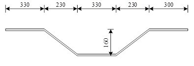
Waveform steel web adopts 1900-type waveform steel plate, and the geometric parameters of the steel web refer to ‘Waveform Steel Web for Combined Structure Bridges’. Horizontal section length and diagonal section length are 0.46m, diagonal section projection length is 0.44m, wave height is 0.27m, bending radius is determined according to the thickness of steel web. Wave-shaped steel web span to the middle pier thickness of 16 ~ 25mm, a total of four thicknesses to change, the specific settings of the thickness of the location according to the calculation to determine. Steel plate material selected Q345D steel moulding method. Single waveform steel web section in the factory welding completed, between sections of waveform steel web processing using site welding [23], [24]. During construction, ordinary bolts are first used for temporary fixation to ensure that the gap between steel plates shall not be greater than 0.8mm, and then welded with fillet welds to achieve the purpose of connecting the waveform steel web between sections [25], [26]. The concrete top plate is connected to the steel web using T-PBL shear keys, and the bottom plate is connected to the steel web using embedded shear keys, with the steel web embedded in the bottom plate at a depth of 500mm. Corrugated steel web embedded part of the opening double rows of holes, hole vertical spacing of 150mm, hole diameter of 40mm, and the use of 30mm diameter rebar for perforation, longitudinal bridge to the round hole every 150mm set one, the upper and lower holes staggered 36mm. waveform steel web bottom welded to the 25mm diameter of the joining steel bar. The connection between the corrugated steel web and the diaphragm (in the direction of the bridge) is made by means of steel bars penetrating through the steel plate, and the connection with the diaphragm (in the direction of the bridge) is made by means of bolts.
The main girder prestressing adopts a hybrid prestressing tendon arrangement with both in-body and out-of-body bundles. The in vivo bundle is used for the top plate bundle during cantilever construction and the top and bottom plate bundles during closing. 15-15 and 15-19 prestressing strands are used for the bundles, and the anchorage adopts the round anchor system. The standard tensile strength of the strand is fpk = 1830 MPa, and the design tension control stress under anchor is fpk = 1830 × 0.75 = 1372.5 MPa. The in-body prestressing aperture adopts plastic bellows and vacuum slurry. The external prestressing adopts 15-22 epoxy coated non-bonded finished cable, tensile standard strength fpk = 1830 MPa, designed tension control stress under anchor fpk = 1830 × 0.6 = 1098 MPa. The structural deadweight and construction stage loads of machinery mainly rely on the prestressing bundles in the box girder of the main bridge to bear. The bridge deck pavement, parapet and vehicle loads mainly rely on the external prestressing for bearing. In order to ensure that the extracorporeal bundles can be easily repaired and replaced, the design requires that the extracorporeal bundles can meet the requirements of multiple tensioning, and puts forward maintenance requirements for anti-corrosion conditions and measures.
(1) Dimensions of box girder. A 40.32m spanning corrugated steel web combined box simple supported girder is selected, and the parameters such as girder height, web inclination angle and form, web thickness and number of spanning diaphragms are changed respectively to carry out comparative study of modal analysis in different working conditions. Figure 1 shows the typical cross section of the box girder when the web inclination angle is 0. The corrugated dimensions of the steel web are shown in Figure 2.
(2) Load condition. In order to verify and compare with the results of modal analysis, and to determine the performance of torsional deformation and warping resistance of the corrugated steel web box girder, two loading conditions are set up in accordance with the specification of the relevant load: symmetric loading and eccentric loading. The influence of car load is considered when loading, and the symmetric and eccentric loads are loaded into two working conditions through the symmetric and eccentric loading arrangement of the car load as follows:
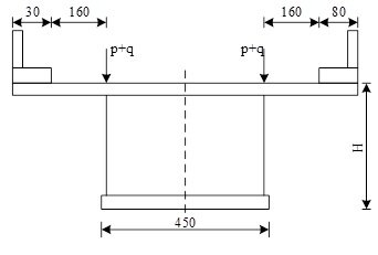
The working condition is as shown in Figure 3, car symmetric loading. The two lane loads are arranged symmetrically. The lane load consists of uniform load q and centralised load p. Its lateral position is arranged according to the vehicle load, and the loading point is taken as the centre line of two wheels, so its distance from the edge of the pavement is 70 + 180 × 0.5 = 160 cm, and the centralised force is laid in the cross section.
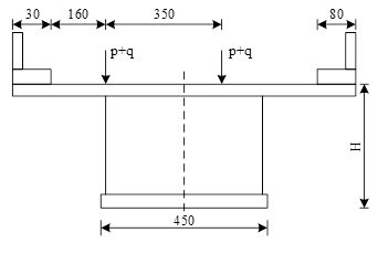
Case 2 is shown in Figure 4, the eccentric load of the car. The load of the two lanes is asymmetrically arranged. The distance between the loading point and the edge of the sidewalk are: 70 + 180×0.5 = 170cm and 140 + 180× 0.5 + 130 + 180×0.5 = 450cm, and the rest are the same as the second working condition, after static analysis, the deflection and normal stress of the middle floor of the box girder span, the shear stress of the web near the fulcrum under the symmetrical load condition are extracted respectively.
(3) Basic assumptions for finite element modelling. It is assumed in the analysis process that the corrugated steel web is completely connected with the concrete top and bottom plates, and no relative slip or shear connection damage occurs. No pre-stressing reinforcement is considered to be involved in the modelling (therefore, large stresses appear in the bottom plate). The corrugated steel web has enough flexural strength, and will not occur any form of flexural damage, without considering the influence of steel reinforcement and concrete nonlinearities, and without considering the involvement of bridge deck pavement.
(4) Finite element modelling. A spatial finite element model is established according to the dimensions of the proposed bridge.
Material properties: the modulus of elasticity of the concrete of the top and bottom slabs is taken as Ec = 3.09 × 10⁴ MPa, Poisson’s ratio vc = 0.1155, and capacity ρc = 28 KN/m3. The modulus of elasticity of the steel web is taken as Es = 2.112 × 10⁵ MPa, Poisson’s ratio vc = 0.3128, and capacity ρc = 73 KN/m3. The modulus of elasticity of the diaphragm is taken as Ec = 3.09 × 10⁴ MPa, Poisson’s ratio vc = 0.1158, and capacity ρc = 28 KN/m3. The tensile strength of the concrete is designed as fcd = 1.381 MPa.
Boundary conditions: fixed hinge support at one end, limiting the UX, UY, UZ, ROTY, ROTZ displacements of the nodes on the base plate here; movable support at the other end, limiting the UX, UY, ROTY, ROTZ displacements of the nodes on the base plate here.
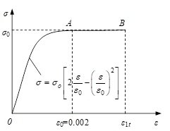
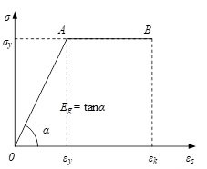
Structure in the calculation of ultimate load carrying capacity, due to the different material properties of concrete and steel, its stress-strain curve shows non-linear, but the material to reach the strength limit is not the only criterion for determining the ultimate load carrying capacity of the structure, but also need to take into account the ductility of the material and the strain limit and other factors. Therefore, the elastic-plastic theory should be used in the calculation of the flexural ultimate load carrying capacity of waveform steel web combined box girder.
(1) Assumptions.
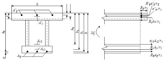
(2) Calculation sketch. Neglecting the thickness changes of the top and bottom flanges of the PC combined box girder with corrugated steel web, both of which are taken as rectangular sections, can be conveniently calculated, and Figure 7 shows the graphical representation of the strength calculation of the positive section.
(3) Basic formula and applicable conditions. The basic formula for the strength of positive section is: It is obtained from the fact that the axial combined force is zero, i.e., \( \sum H = 0 \):
\[ R_g A_g + R_y A_{y1} + \sigma_{yu} A_{y2} = R_{ab} c x + R’_g A’_g + \sigma’_{yu} A’_y \tag{1} \]
Moment is taken for the point of action of the combined forces of the ordinary reinforcement in the compression zone, \( \sum M = 0 \) (where 0.9 is the coefficient by which \( M_u \) is multiplied when bias loads are taken into account):
\[ M_u = \frac{0.9}{r_s} R_g A_g (h_g – h’_g) + \frac{0.9}{r_s} R_y A_{y1} (h_{y1} – h’_g) + \frac{0.9}{r_s} \sigma_{yu} A_{y2} (h_{y2} – h’_g) + \frac{0.9}{r_s} \sigma’_{ya} A’_y (h’_y – h’_g) – \frac{0.9}{r_c} R_{ab} c x \left(\frac{x}{2} – h’_g\right) \tag{2} \]
The applicable conditions are:
\[ \left\{ \begin{array}{l} x \geq 2 h’_g \\ x \leq \xi_j h_0 \quad \text{(generally met)} \end{array} \right. \tag{3} \]
Among them:
\[ h_0 = \frac{R_g A_g h_g + R_y A_{y1} h_{y1} + \sigma_{yu} A_{y2} h_{y2}}{R_g A_g + R_y A_{y1} + \sigma_{yu} A_{y2}} \tag{4} \]
where
Regarding the shear buckling of corrugated steel webs, research scholars have done a lot of experimental research and theoretical analysis work. There are three modes of shear buckling of web plates: local buckling, overall buckling and combined buckling. Local buckling occurs in a single plate or even the entire web. Combined buckling has the damage characteristics of both. The dominant buckling of corrugated steel webs is influenced by the sparseness of the corrugation, and when the corrugation is sparse, local buckling dominates. When the corrugation is dense, the overall buckling is dominant.
(1) Local buckling. Local shear buckling can be regarded as the buckling of individual laths under uniform shear stresses, and the yield strength of local buckling has been calculated from classical theoretical derivations. The Skan-Southwell formula expresses the local yield strength \( \tau_{cr,L} \) calculated as:
\[ \tau_{cr,L} = \frac{\pi^2 E}{12(1 – \mu^2)} \left( \frac{t}{b_w} \right)^2 k, \]
where \( E \) is the modulus of elasticity of the centre steel plate, \( b_w \) is the width of the longer of the corrugated steel web flat plate \( a \) and diagonal plate \( c \), i.e., \( b_w = \max\{a, c\} \), \( \mu \) is the Poisson’s ratio of the corrugated steel and \( k \) is the coefficient determined by the aspect ratio \( b_w/h_w \) of the plate and boundary conditions.
The value of \( k \) of the waveform steel plate is taken as follows:
When the long side of the waveform steel plate is simply supported and the short side is fixed:
\[ k = 5.34 + 2.31 \left( \frac{b_w}{h_w} \right) – 3.44 \left( \frac{b_w}{h_w} \right)^2 + 8.39 \left( \frac{b_w}{h_w} \right)^3. \tag{6} \]
When the corrugated steel plate is simply supported on all four sides:
\[ k = 5.34 + 4.0 \left( \frac{b_w}{h_w} \right)^2. \tag{7} \]
When the waveform steel plate is fixed on all four sides:
\[ k = 8.98 + 5.6 \left( \frac{b_w}{h_w} \right)^2. \tag{8} \]
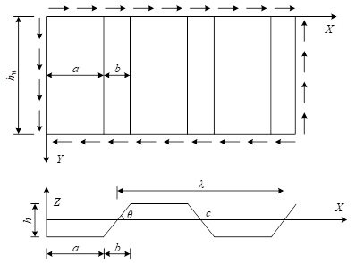
(2) Overall buckling.Figure 8 illustrates the calculation of overall buckling of corrugated steel plate. Integral buckling is to consider the corrugated steel web as an orthotropic anisotropic plate, which is elastically supported on all four sides, and buckling occurs under the action of shear stresses through a number of laths or even the entire web. The height and length of the web, as well as the wave height of the corrugations, affect the occurrence of overall buckling.
The overall shear compression flexural strength of a corrugated steel web plate was derived using the energy method, in which he considered the corrugated plate as an orthogonal anisotropic plate simply supported at both ends, and derived the shear flexural load \( N_{cr} \) per unit length of the corrugated plate, which is expressed as:
\[ N_{cr} = 36 \beta \frac{D_y^{1/4} D_x^{3/4}}{h_w^2}, \tag{9} \]
where \( D_x \) and \( D_y \) represent the bending stiffness per unit length of the corrugated plate section along the \( x \)-axis and \( y \)-axis, respectively.
The parameter \( \beta \) is the boundary coefficient associated with the \( y \)-axis of the corrugated plate. It typically ranges between \( 1 \leq \beta \leq 1.9 \). For a web with both sides fixed, \( \beta = 1.9 \), and for simply supported conditions, \( \beta = 1.0 \).
The overall shear yield strength can be derived from the shear buckling load \( \tau_{cr,G} \) as follows:
\[ \tau_{cr,G} = \frac{N_{cr}}{t} = \frac{36 \beta D_y^{1/4} D_x^{3/4}}{h_w^2 t}, \tag{10} \]
\[ D_x = \frac{EI_x}{\lambda} = \frac{E}{\lambda} \left[ 2a t \left( \frac{h}{2} \right)^2 + \frac{2}{\sin \theta} \cdot \frac{th^3}{12} \right], \tag{11} \]
\[ D_y = \frac{\lambda}{s} EI_y = \frac{\lambda E}{s} \cdot \frac{t^3}{12}, \tag{12} \]
where, \( \lambda \) is the wavelength of the corrugated steel web, \( E \) is the elastic modulus of the corrugated steel, \( h_w \) is the vertical height of the corrugated steel web and \( s \) is the actual length of one wavelength along the steel web.
Therefore, the expression for the overall flexural shear strength \( \tau_{cr,G} \) of the corrugated steel web is:
\[ \tau_{cr,G} = \frac{36\beta}{\sqrt{96}} \left[ \frac{\lambda}{s} \left( \frac{h}{\lambda} \right)^3 \left( \frac{a}{h} + \frac{1}{3 \sin \theta} \right)^3 \right]^{1/4} \cdot \frac{h \sqrt{ht}}{h_w^2} E = \frac{36 \beta}{\sqrt{96}} \cdot p_g \cdot \frac{h \sqrt{ht}}{h_w^2} E, \tag{13} \]
where \[ p_g = \left[ \frac{\lambda}{s} \left( \frac{h}{\lambda} \right)^3 \left( \frac{a}{h} + \frac{1}{3 \sin \theta} \right)^3 \right]^{1/4} \] is a dimensionless geometric parameter.
For specific corrugated web types:
Wave height (h): The flexural strength \( \tau_{cr,G} \) is directly proportional to \( h \sqrt{ht} \). A higher wave height leads to greater flexural strength, suggesting that increasing wave height can enhance the flexural capacity and safety margin of the corrugated steel web. This insight supports more efficient design, balancing structural performance and economic feasibility.
Wave height (\( h_w \)): The strength \( \tau_{cr,G} \) is inversely proportional to \( h_w^2 \). This implies that the height of the web plays a critical role in overall buckling behavior. In deep corrugated webs, the risk of global buckling increases significantly, and this factor must be carefully considered in the design of deep steel beams.
(3) Combined Buckling. Combined buckling refers to a buckling mode in which local buckling and global (overall) buckling occur simultaneously and interact with each other. This failure mode typically arises suddenly and is often accompanied by a sharp noise, followed by visible plastic deformation along the folding line of the bent plate.
Shotai Kondo et al. (Japan) derived an expression for the combined shear-flexural buckling strength, denoted by \( \tau_{cr} \), as follows:
\[ \frac{1}{\tau_{cr}} = \frac{1}{\tau_{cr,L}^4} + \frac{1}{\tau_{cr,G}^4}, \tag{14} \]
where \( \tau_{cr,L} \) and \( \tau_{cr,G} \) represent the local and overall buckling strengths, respectively.
In practical bridge engineering applications, the material properties and geometric parameters of each corrugated steel web can significantly influence the shear buckling behavior, which is often the primary control mode for design. The buckling mode—whether local, overall, or combined—directly determines the allowable shear stress. Therefore, it is essential to evaluate the shear strength for all three buckling modes and conduct a comprehensive strength verification of the steel web.
The allowable shear strengths corresponding to local buckling, overall buckling, and combined buckling of the corrugated steel web are defined as:
\[ [\tau_L] = \frac{\tau_{cr,L}}{\gamma_L}, \tag{15} \] \[ [\tau_G] = \frac{\tau_{cr,G}}{\gamma_G}, \tag{16} \] \[ [\tau_{cr}] = \frac{\tau_{cr}}{\gamma_{cr}}, \tag{17} \]
A mega-span partial cable-stayed bridge is located on the east side of the intersection of Century Avenue and Baizhang East Road, which is a bridge with a new type of structure in the new river bridge group of the eastern new town, and also an important traffic channel between the old town and the new town. The upper structure is a three-span multi-box chamber continuous variable cross-section box girder structure, span combination of 30+55+30m, the bridge transverse width of 55m, consisting of separated 5 boxes and single chamber cross-section, the box girder is rigidly connected by the 0.5m wide backing belt wet header in the middle of the wing plate. The height of the outer edge beam of the abutment bearing section is 2.5m, the height of the outer edge beam of the mid-span section is 1m, the bottom plate of the box girder is horizontal, and the cross slope of the bridge deck is adjusted out of the height of the web. The bottom edge of the box girder is in the form of a circular arc. There are 3 × 5m long two-stage lap boards on each side of the bridge. The bridge is orthogonal to the river. A convex vertical curve of R = 1200m is provided at the centre of the bridge, with 2.88% two-way longitudinal slopes on both sides. The carriageway has an outward 2.2 per cent cross slope and the footway has an inward 2.3 per cent cross slope.
Structure in the abutment on both sides of each 15m range of waveform steel web, other beam height is relatively low section using concrete box girder. Single box girder bottom width of 6m, the middle beam top width of 12m, side beam top width of 12m, web width of 60cm, top plate thickness of 40cm. variable thickness of the bottom plate, span thickness of 40cm, pier pivot point thickness of 80cm, using C50 concrete. There is a crossbeam at the pier, 120cm thick, and there is a 1m thick cross partition in the middle span, and there is a 40cm thick cross partition at each end of the steel web.
In highway bridges, the trajectory of the car on the bridge has a certain degree of randomness, and in many cases, the car load makes the bridge in the state of bias load. At present, in the actual calculation process of the bridge, the method of amplification coefficient of automobile load bias is commonly used to consider the unfavourable effects of automobile load bias. For the selected cross-section of the study, the load is carried out in two cases, case 1 is symmetric load (mentioned in 2.1.4 above), and case 2 is eccentric load (mentioned in 2.1.4 above), and the ratio of the maximum value of the load effect between case 2 and case 1 is the vehicle load bias amplification factor, which reflects the structural design effect of corrugated steel webs box girders in modern bridges through the vehicle load bias amplification factor.
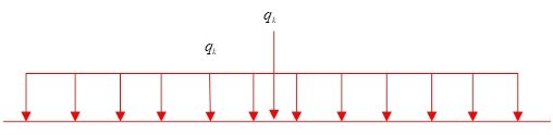
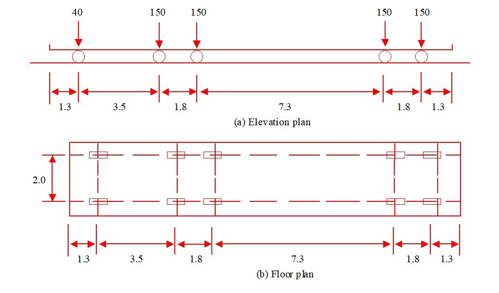
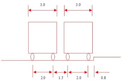
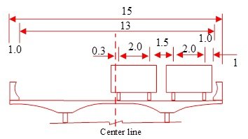
Take the mid-span centre section as an example to illustrate the specific loading forms of Case 1 and Case 2. Firstly, the maximum positive bending moment value M1 of the mid-span cross-section under the action of lane load is found by affecting the line load. The form of lane load in the General Design Specification for Highway Bridges and Culverts is shown in Figure 9, and the load length of uniform load qk is unlimited in the process of application, and the centralised load is applied to the most unfavourable position, and lane load is the elevation load, which can not reflect the transverse distribution of the car load, and the consideration of the Offset load. The form of vehicle loading in the General Design Specification for Highway Bridges and Culverts is shown in Figure 10, in which 10(a)~10(b) are the elevation layout and plan layout respectively, and the vehicle loading can realise the bias load arrangement of the vehicle loading. Arrange the vehicle load based on the bending moment influence line of the mid-span cross-section to get the maximum bending moment M2 of the mid-span cross-section, which theoretically should ensure that M2 and M1 are completely equal, which is actually difficult to achieve. With reference to the “highway bridge load test regulations” on the efficiency of the bridge static load test, when the ratio of M2 and M1 in the 0.85~1.05 can be, this paper in the calculation, as far as possible to ensure that the value is close to 1. Vehicle load in the elevation of the position is determined, according to the plane of the different positions are divided into symmetric load – condition 1, eccentric load – condition 2. -Case 2. For symmetrical loading, the vehicle loads are arranged symmetrically about the centreline of the box girder. The minimum spacing dimensions for lateral arrangement of vehicle load in ‘General Design Code for Highway Bridges and Culverts’ are shown in Figure 11, the minimum distance between the outer axle of the outermost vehicle and the edge of the carriageway is 0.8 m, and the minimum axle distance of two vehicles is 1.5 m. The arrangement of Case 2 is based on the above two indexes, and the arrangement of the vehicle load bias loading is shown in Figure 12, with the width of the bridge deck of 15 m, and the net width of the carriageway of 13 m. The bias load effect of the cross-section is the largest when arranging two vehicles, so when determining M2, there are at most two vehicles arranged at the same elevation position. Section of the bias load effect is the largest, so in determining the M2, the same elevation position at most two vehicles.
The maximum positive bending moment of the mid-span section determined by the lane load is M1= 27296kN-m, and the maximum positive bending moment of the mid-span section determined by the vehicle load is M2= 27234kN-m, M2/M1=1.002. Symmetrical load Case 1 has a total of 7 standard vehicle loads, and the elevation of Case 2 (bias load) is exactly the same as that of Case 1. The position is exactly the same as that of Case 1.
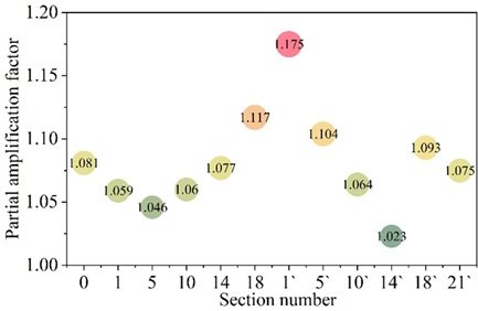
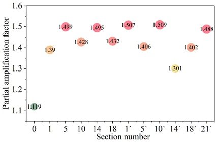
Next, with the help of spatial finite element model ANSYS, the amplification factor of car load bias was calculated for the cross sections of Case 1 (0, 1, 5, 10, 14, 18) and Case 2 (1′, 5′, 10′, 14′, 18′, 21′), respectively, and the envelopes of the amplification factor of the car load bias for the car load positive stress are shown in Figure 13, and that for the car load bias for the car load shear stress are shown in Figure 14. In all calculated sections, the car load positive stress bias load magnification factor is between 1.02 and 1.20, and the car load shear stress bias load magnification factor is between 1.10 and 1.51. From the calculation results, the influence of vehicle load bias effect on shear stress is greater than that of positive stress in the improved large-span corrugated steel web composite box girder bridge. In addition, the positive stress bias load magnification factor and the shear stress bias load magnification factor should be taken separately to be more in line with the reality. The car load positive stress bias amplification factor of 1.20 and the car load shear stress bias amplification factor of 1.51 can encompass the results of all sections, which indicates that when designing modern bridges, the car load positive stress bias amplification factor can refer to the value of 1.15 and the car load shear stress bias amplification factor can refer to the value of 1.51, and then the designed bridges will have significant stability.
In this subsection, the experimental study of the flexural ultimate load carrying capacity of two box girders with corrugated steel webs is carried out, the test girders are numbered as A and B. The design parameters of the two girders are the same, and the comparison between the formulae values of the flexural ultimate load carrying capacity and the test values is shown in Table 1. From the table, it can be seen that the deviation of the calculation of the ultimate bending moment using the formula is within 15%, and the difference between the ultimate torque value and the test value is small, with an error of 15% or less. Overall, the error between the calculated value and the test value of the ultimate bearing capacity formula proposed in this paper is within 15%, which meets the accuracy requirements of the design calculation and can be used to guide the engineering design.
| No. | Loading bending and torsion ratio | Ultimate bending moment (kN·m) | Ultimate torque (kN·m) | ||||
|---|---|---|---|---|---|---|---|
| Experimental value | Formula value | Ratio | Experimental value | Formula value | Ratio | ||
| A | 0.5 | 64.8 | 62.6 | 1.03 | 176.13 | 196.22 | 0.90 |
| B | 1 | 156.4 | 199.6 | 0.78 | 164.72 | 162.23 | 1.01 |
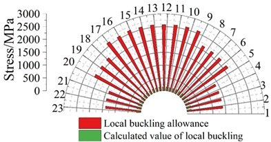
(1) Local buckling calculation of corrugated steel web plate. Here, the corrugated steel web is divided into 1∼23 units, and there is no conflict between the numbering here and the previous section. According to the above formula for the local buckling of corrugated steel webs, the results of local buckling of corrugated steel webs are shown in Figure 15. The data show that the minimum local buckling critical strength of the corrugated steel web is 1359.24 MPa, which is greater than the yield shear stress of 183.55 MPa, and the local buckling calculation of the corrugated steel web meets the specification requirements.
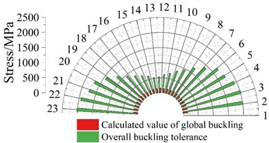
(2) Buckling calculation of the waveform steel web plate as a whole. Similarly, according to the formula, calculate the overall elasticity of the corrugated steel web plate yielding critical shear stress, the overall yielding results of the corrugated steel web plate is shown in Figure 16. The minimum overall buckling critical strength of the corrugated steel web is 545.76 MPa, which is greater than the yield shear stress of 169.24 MPa, and the overall buckling of the corrugated steel web meets the requirements of the bridge standard, and at the same time expresses that the corrugated steel web has good mechanical properties.
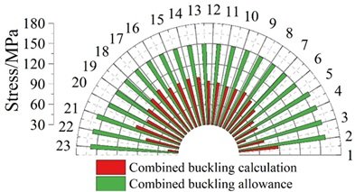
(3) Buckling calculation of corrugated steel web combination. The results of the combined buckling calculation of the corrugated steel web plate are shown in Figure 17. Under the load capacity limit state, the most unfavourable value of the combined yield strength of the corrugated steel web is 104.78MPa, which is smaller than the combined yield critical shear stress of 149.42MPa, and the combined yield calculation of the corrugated steel web meets the design requirements of the bridge design, which highlights the excellent mechanical performance.
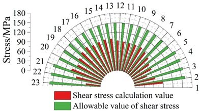
The results of shear stress strength analysis are shown in Figure 18. According to the material standard, the shear design value of Q345 steel plate with thickness of 16mm and below is 170MPa, and the shear design value of Q345 steel plate with thickness of 16-35mm is 161MPa. According to the standard calculation, the shear stress intensity of corrugated steel web at the limit state of load carrying capacity is calculated. Under the basic combination of load-bearing capacity limit state, the shear stress of corrugated steel web plate is less than the design allowable value, and its shear stress strength is in full compliance with the bridge design standards and requirements.
In this paper, the corrugated steel web box girder is applied to the design of modern bridge structure and its mechanical properties are analysed with the help of spatial finite element model.
(1) The maximum positive bending moment of section M1 of working condition 1 (symmetric load) =27296kNm, while the maximum positive bending moment of section M2 of working condition 2 (partial load) =27234kNm, the corresponding partial load amplification factor of automobile load is 1.002, and the load of (symmetric load) working condition 1 is a total of 7 standard vehicles. (partial load) the elevation position of working condition 2 is completely consistent with that of working condition 1. In addition, it can be concluded that when designing modern bridges, the vehicle load positive stress bias amplification factor can refer to a value of 1.15, and the vehicle load shear stress bias amplification factor can refer to a value of 1.51, which is conducive to improving the stability of bridges.
(2) The error between the calculated value of the ultimate bearing capacity formula and the test value of the two corrugated steel web box girders is within 15%, which is in full compliance with the accuracy requirements of modern bridge design, and the rest of the shear buckling and shear stress strength tests meet the bridge design requirements.
This research was supported by the Nationa Science Foundation Project: Analysis and Experimental Study on the Torsional Mechanical Performance of Corrugated Steel Web Prestressed Concrete Composite Box Girders (Project Number: 51568036).