
Traditionally, machine designers have predominantly employed rigid-body dynamic analysis methods, treating all mechanism components as rigid bodies. Following dynamic analysis, force and stress analysis of the rigid members is conducted, yielding reasonably accurate results when machine speeds are significantly lower than the natural frequencies of the system. However, the demand for higher-speed operation with increased positioning accuracy and force per unit mass has necessitated vibration analysis to predict mechanism response and stability during operation. Unstable parametric resonant conditions can lead to significant elastic deformations and premature fatigue failure due to the coupling of high stress levels and cyclic occurrence.
In response to these challenges, considerable research has emerged, as documented in previous works. Broadly, this research can be categorized into two groups: those treating elastic links as continuous systems and those treating them as discrete systems with a finite number of degrees of freedom. Building upon this, a derivation of generalized equations of motion for elastic mechanism systems was presented, employing displacement finite elements as the mathematical model. The approach’s versatility is showcased through its application to a high-speed punching machine featuring a geometrically complex follower link modeled with linear quadrilateral finite elements. For detailed theoretical developments, readers are directed to the d work.
The equations of motion for the entire mechanism system are expressed as follows:
\[\begin{aligned} [M] \{\mathbf{\ddot{x}}\} + [C] \{\mathbf{\dot{x}}\} + [K] \{\mathbf{x}\} &= \{\mathbf{F_{\text{ext}}}\} – [M_d] \{\mathbf{\ddot{X}_0}\} – 2 \left( [M_{dd}] + [M_{\omega A}] \right) \{\mathbf{x}\} \\ &\quad – \left( [M_{\text{acc}}] + 2[M_{\dot{\mathbf{x}}\text{vel}}] \right) \{\mathbf{\dot{x}}\} \end{aligned} \label{eq:1}\tag{1}\]
Here, \([M]\), \([C]\), and \([K]\) represent the system mass, viscous damping, and stiffness matrices, respectively. \(\{\mathbf{x}\}\), \(\{\mathbf{\dot{x}}\}\), \(\{\mathbf{\ddot{x}}\}\), and \(\{\mathbf{\ddot{X}_0}\}\) contain the displacement, velocity, acceleration, and rigid-body acceleration, respectively, of the degrees-of-freedom describing the mechanism system. The generalized forces are contained in \(\{\mathbf{F_{\text{ext}}}\}\). The matrices \([M_d]\), \([M_{\dot{\mathbf{x}}\text{vel}}]\), \([M_{dd}]\), \([M_{\omega A}]\), and \([M_{\text{acc}}]\) involve mass distribution and rigid-body orientation, velocity, and acceleration. For detailed derivation, see [1].
The coefficient matrices in equation (1) are periodic functions of the mechanism position due to the transformation matrix \([T_R]\) described in [], which is necessary for compatibility of displacement, velocity, and acceleration of degrees-of-freedom common to two or more links. For a mechanism operating at a constant speed, these matrices will be position- and time-periodic. The approach used to solve the equations of motion (1) was developed by Midha [2], which is capable of calculating transient and steady-state response of a linear second-order differential equation with time-periodic coefficients efficiently.
Equation (1) represents a coupled set of differential equations that must be decoupled. This procedure is complicated by the presence of nonsymmetric matrices \([M_d]\), \([M_{dd}]\), \([M_{\dot{\mathbf{x}}\text{vel}}]\), \([M_{\omega A}]\), and \([M_{\text{acc}}]\). Neglecting the coupling terms temporarily, equation (1) simplifies to:
\[\{\mathbf{\ddot{x}}\} + [C] \{\mathbf{\dot{x}}\} + [K] \{\mathbf{x}\} = \{\mathbf{F_{\text{ext}}}\} – [M_d] \{\mathbf{\ddot{X}_0}\} \label{eq:2}\tag{2}\]
This simplified equation can be decoupled using modal analysis techniques [3–6], allowing Midha’s steady-state solution algorithm [2] to be applied to obtain the steady-state solution directly.
For additional context, references are made to:
Transformation matrix \([T_R]\) for the compatibility of displacement, velocity, and acceleration across multiple links.
Midha’s algorithm for the transient and steady-state response of time-periodic systems.
Modal analysis techniques for decoupling differential equations.
The complete derivation and solution approach detailed in the cited works [1–6].
In general, machine designers have traditionally relied upon rigid-body dynamic analysis methods, wherein all mechanism members are treated as rigid bodies. Subsequent to the dynamic analysis, a force and stress analysis of the rigid members is undertaken. This approach tends to be reasonably accurate as long as the speed of machine operation remains very much lower than the natural frequencies of the mechanism system.
As pointed out earlier [5], mechanisms are now being required to run at higher speeds while maintaining greater positioning accuracy, and exerting a greater force per unit mass of the mechanism. A vibration analysis is necessitated to predict the mechanism response and its stability during operation. Unstable parametric resonant conditions would not only result in large elastic deformations, but would also shorten the life of the mechanism due to early fatigue failure. The latter results from coupling of high stress levels and their cyclic occurrence.
It is, therefore, not surprising that much research has been reported in recent years addressing the above issues. A representative set of these works are reported in [6]. By and large these works have been divided into two categories, the first being works of those researchers who treated the elastic links of four-bar or slider-crank mechanisms as continuous systems. A second group treated the elastic links as discrete systems, wherein a finite number of degrees-of-freedom are utilized to describe the motion of the discretized system.
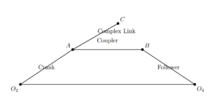
It was in this latter vein that [3] presented a derivation of the generalized equations of motion for elastic mechanism systems. The mathematical model utilizes the displacement finite elements. The reader is referred to [2] for detailed theoretical developments. The generality of the approach is exemplified here by its application to a high-speed, four-bar, punching machine, whose geometrically complex follower link is modeled with linear quadrilateral finite elements.
The equations of motion for the entire mechanism system have been expressed as follows: \[\mathbf{x}^{(i)} + [Q]\mathbf{x}^{(i-1)} + [K]\mathbf{x}^{(i)} = \mathbf{Q}_{\text{ex}} – [M]\mathbf{x}_0 – 2\left( [M_d] + [M_{\text{vel}}] \right)\mathbf{x}^{(i)} – \left( [M_{\text{dd}}] + 2[M_{\text{vel}}] + [M_{\text{acc}}] \right)\mathbf{x}^{(i-1)}\tag{3}\] where subscript \(i\) denotes the iteration number. The iteration proceeds as follows. In the first iteration, \(i = 1\) and \(\mathbf{x}^{(0)} = \mathbf{w} = \mathbf{0}\), and the following equation is solved for \(\mathbf{x}^{(1)}\) and \(\mathbf{w}\), in each time subinterval: \[\mathbf{x}^{(1)} + [Q]\mathbf{w} + [A]\mathbf{w} = \mathbf{Q}_w – [A]\mathbf{x}^{(0)}\tag{4}\] In the second iteration, the values of \(\mathbf{x}^{(1)}\) and \(\mathbf{w}\) are substituted into the right-hand side of equation (1) and the improved solution (\(\mathbf{x}^{(2)}, \mathbf{w}^{(2)}\)) is evaluated. This procedure is repeated until the changes in the \(\mathbf{x}\) and \(\mathbf{w}\) vectors, for each point in the time period, meet some predetermined small value.
The recursive scheme proved to be efficient and converged in very few (less than 5) iterations for the cases examined. It should be noted that each of these cases produced only small changes from the original or base solution. Inaccuracy problems could occur if the rigid-body and elastic motion coupling terms were to cause large variations from the base solution. Presently, in the iterative procedure, the eigenvalues and eigenvectors of equation (1) are assumed to remain unaffected by the rigid-body and elastic motion coupling terms. Therefore, if the coupling terms significantly change the eigenvalues and eigenvectors of the original system, a variation of the above iteration procedure would be necessary which takes the large changes into account. At this point, the recursive scheme is used only as a means for determining whether the coupling terms are significant. For the cases examined thus far the coupling terms proved to be negligible.
The four-bar mechanism with a geometrically complex follower link is modeled with linear quadrilateral finite elements [5–8]. The finite element model contains 241 elastic degrees-of-freedom. This particular mechanism constitutes part of a high-speed punching machine. The various parameters associated with the mechanism. Two separate approaches are taken to determine stresses in the punching mechanism, as it operates at 5000 rpm. The first is a quasi-static analysis, that assumes the velocity (\(\dot{x}\)) and acceleration (\(\ddot{x}\)) corresponding to the generalized coordinates [5] to be negligible. The quasi-static method is traditionally the method of design for industrial mechanisms. The second method is a vibration analysis based on the methods developed in [1]. The stresses determined by the two methods are then compared.
These results indicate that a realistic mechanism of this type could be undersigned if the vibratory response were not taken into account.
In conclusion, the analysis of the geometrically complex four-bar mechanism revealed significant insights into the behavior of high-speed industrial machines. Through the quasi-static and vibration analyses, we observed distinct differences in stress distributions and mechanical responses. The quasi-static method, although traditionally employed in industrial design, tended to underestimate stresses compared to the vibration analysis. The latter, based on dynamic considerations, highlighted the importance of accounting for the vibratory response, particularly in mechanisms operating at high speeds.
Furthermore, the study showcased the efficacy of finite element modeling in capturing the intricate behavior of elastic mechanisms. By employing linear quadrilateral finite elements, we were able to simulate the complex follower link with 241 elastic degrees-of-freedom, providing a detailed understanding of stress distributions under varying operating conditions. These findings underscore the necessity of integrating dynamic analysis techniques into the design process of industrial mechanisms, ensuring their structural integrity and performance under real-world operating conditions.
Overall, the comparison between quasi-static and vibration analyses emphasized the critical role of dynamic considerations in accurate stress prediction and highlighted potential risks associated with neglecting vibratory responses in mechanism design. This study serves as a valuable for engineers and designers, advocating for the adoption of comprehensive dynamic analysis methods in the development of high-speed mechanical systems.